Workspace Basics
Add a Step Button
.3cf116cc.png)
Positioning the mouse over an End node will reveal a +. Clicking on this opens the Add Step Menu.
Role Legend
Actions are color coded based on the role assigned. The Role Legend at the bottom left corner of the workspace shows all defined roles and the corresponding color.
.c37094e2.png)
Scrolling and Zooming in the builder
The workspace is an endless canvas, so even the most complex processes can be modelled. The Workspace can easily be navigated by scrolling and zooming. here are some tips to scrolling and zooming depending on the operating system and pointing device you are using:
| Operating System | Device | Instructions |
|---|---|---|
| macOS | Touchpad | Scrolling and Zooming use standard multi-touch gestures |
| Microsoft Windows | Touchpad | |
| Microsoft Windows | Mouse (Scroll Wheel) | ctrl + Scroll up - zooms in where mouse is. |
| Linux | Touchpad | Ctrl + Scroll for Zoom |
| Linux | Mouse |
Workspace Right-Click Menu
Right-Clicking in an empty portion of the Workspace opens the Right-Click Menu.
.579c587d.png)
Add Favorite Step: a shortcut to access your step favorites.
Add Step: opens the Add Actions Dialog
Add Note: adds a note to the workspace
Add Data: opens the Add Data Dialog where you can directly create new variables and constants.
Format Process: this repositions all the steps.
Format Process does not move Notes.
Paste: is not currently available and is disabled.
Add a Note
While building a process, it is sometime helpful to leave a note to yourself or to others working on the process. They can be added using the Right-Click Menu in the Workspace. Notes can be dragged and dropped. They automatically resize. Notes are only visible in the Builder.
.87ba54ea.png)
Step Status Indicators
.dc2e80d4.png) | Colored no glow: Role is assigned and the step is completly configured |
.338f38e2.png) | Glowing Red: The step is currently invalid due to a missing configuration. .d863a4ad.png) |
.0bbb9f07.png) | Enlarged and Pulsating Green: The step is currently selected and loaded in the Configurator |
Connecting Steps
Connections are visualised as green, black and red dashed lines. They are animated to show the direction to the next step.
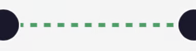 | Green Lines are standard. The represent a postive outcome of the step |
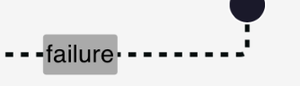 | Black Lines represent a negative branch from an step such as Review and Conditional. They are tagged with failure |
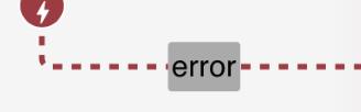 | Red Lines represent an error handling branch from a step where error handling has been toggled on. They are tagged with error |
Steps which are added directly from the end node .230b3013.png) are connected automatically. When a step is added via the right-click menu, it is not connected. To connect the either drag the end node to the step you want to connect to, or click on the start note and drag it back to the node you want to connect to.
are connected automatically. When a step is added via the right-click menu, it is not connected. To connect the either drag the end node to the step you want to connect to, or click on the start note and drag it back to the node you want to connect to.
Only steps connected to the main process will show the end node
Breaking a Connection
Connections can be removed by right-clicking directly on the connection to be removed. Connections can also be removed from the connections section of the Configurator. .7594e5c6.png)
Viewing Connections (Configurator)
All incoming, outgoing and error connections can be viewed in the Configurator. .7594e5c6.png)
Multiple Connections
A step can have multiple Outgoing (Branching) or multiple Incoming (Merging) connections. Branching and Merging Logic needs to be defined accordingly. More information on Branching and Merging can be found here.
Step Right-Click Menu
right clicking directly on a step opens the Instruction Actions Menu
Copy: is not currently available and is disabled
Delete: deletes the step
Toggle Error Handling: Adds a Error Handling Node under the given step. See Error Handling
.c8012f65.png)